Getting started with AVR programming
Is Arduino a bit too simple? If you want to get your hands dirty and program the AVR microcontroller directly, here is a guide on how to do it on OS X.
After Arduino
So you tried Arduino programming. It is a great way to get introduced to Microcontrollers. But if you are actually an experienced programmer it doesn’t quite feel like the real thing. It is sort of like learning BASIC when you know there is this other thing real programmers use which is C.
Arduino is built around the AVR microcontroller. It simplifies a lot by providing a USB port on the board itself and having a loaded program to load your program into the memory of the AVR microcontroller. If you want to program an AVR chip directly without having all the Arduino infrastructure, then you need a piece of hardware called a programmer and software such as AVRdude.
The problem getting started with this is that the information related to it is scattered all around the internet. This is my attempt to collect it all in one guide.
What software to get
First get CrossPack. It is a collection of tools for programming AVR chips on OS X. The most important part being AVRDUDE. The next thing you need to do is bookmark AVR fuse calculator. When programming AVR there are something called fuse bits. There are bits which you store in flash memory which affect how the AVR chip will work. It is important to not screw up these settings because if you do it wrong you might not be able to program it again. The fuse bits can be used to set the way the AVR chip should be programmed.
Hardware
When developing electronics projects I prefer to have the important data sheets printed out. So I recommend printing out the ATtiny13 datasheet found at atmel.com. And if you like me use the AVR-ISP500 programmer from Olimex get its manual.
Now I am not going to repeat all the great information found in all these data sheets and manual, but I will try to fill in the blanks. Connecting all this information to get you to program your AVR chip is not always straight forward.
Setting up the software
Follow the tutorial at CrossPack. You then get a Makefile containing these settings:
DEVICE = atmega8
CLOCK = 8000000
PROGRAMMER = #-c stk500v2 -P avrdoper
OBJECTS = main.o
FUSES = -U hfuse:w:0xd9:m -U lfuse:w:0x24:m
The problem is figuring what these settings should be for your device. You can write:
avrdude -c stk500v2
To get a list over supported AVR chips, or parts as AVRDUDE will refer to them. But really the easiest way to write the DEVICE name is to just write the name of the chip is small letters. So ATtiny13 becomes attiny13. I actually have a ATtiny13V, but you should not add the V. It is not really a significantly different model.
The next problem is specifying the programmer. This can be confusing. You do not actually write AVR-ISP500, even though that is what you have. What matters is the protocol. The AVR-ISP500 uses the STK500v2 protocol, so that is what matters to AVRDUDE. This is probably because mutliple manufactureres probably make programmers which act the same, but they need to be given unqiue names to distinguish each product.
Now you might think that you should supply avrdoper to the -P argument. But that is for another programmer implementing the STK500v2 protocol. If the programmer acted as a regular USB devices you could just write -P USB. But AVR-ISP500 uses a serial port over USB. I do not really know what that means. It is sort of like emulating a serial port over USB. So this serial port only exists logically on your Mac not physically. This gives problems when trying to find it on your Mac. You can write:
$ ls /dev/cu.*
/dev/cu.Bluetooth-Modem    /dev/cu.Bluetooth-PDA-Sync
to get a list of serial devices. Unfortunatly our serial device is not there. That is because it is logical and created on the fly. So you have to actually plug in your AVR-ISP500 into the USB port before it pops up in the list. The name will be different for different computers. On my computer it shows up as /dev/cu.usbmodemfa121.
Now the final setting to figure out are the fuses. I got mine from chapter 1, page 28 of the book tinyAVR Microcontroller Projects for the Evil Genius. They set high fuse to 0xFF and low fuse to 0x73. Those bits will mean different things for different AVR chips. To find out what it means go to the AVR Fuse Calculator chose your AVR chip. In my case ATtiny13. Scroll down past all the individual fuse bits and input the high and low fuse bits 0xFF and 0x73. That means we do not enable any of the high bits because, you need to set a bit to 0 to enable it. On the low bits we enable SPIEN, SUT1 and SUT0. The important part is that we enable the SPIEN bit, because that is what allows us to program the AVR chip using a serial interface called SPI. That is what AVR-ISP500 uses. So the important section in my Makefile ended up being changed to:
DEVICE = attiny13
CLOCK = 8000000
PROGRAMMER = -c stk500v2 -P /dev/cu.usbmodemfa121
OBJECTS = main.o
FUSES = -U lfuse:w:0x73:m -U hfuse:w:0xff:m
Now we got the software configured. What is left is getting the hardware configured.
Configure the Hardware
Before going into details, let me just tell you that hooking up the programmer to your AVR chip is a lot easier than I thought at first. You do not really need to put in any extra components: capacitors, resistors etc. You do not even need to supply a power source. The programmer will give you everything including power through its cable.
Just put your AVR chip down on the breadboard. Look at your AVR-ISP500 manual and your ATtiny13 datasheet and make sure you connect the 6 pins from your programmer to the right 6 pins on your AVR chip. Here are some tips for each pin:
- Serial input (abbriviated MISO) goes from pin 1 on programmer to pin 6 on ATtiny13
- Target VCC is the same as VCC on your AVR chip. This is how the chip gets power.
- Serial clock connects to pin 7 on AVR
- Serial output (MOSI) to pin 5
- Target reset connects to pin 1 on your ATtiny, which is the reset pin. When it goes LOW it will reset the chip. E.g. starting program over again.
- Ground (GND). Connect to pin 4, which is GND on the AVR.
If you pull out the cable it is easy to compare with the Olimex manual.
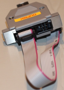
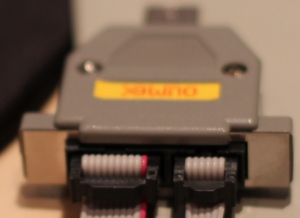
AVR-ISP500 USB based AVR programmer from Olimex, implementing STK500v2 protocol
A thing to note about the cable is the pins get turn upside down. So if you turn the programmer so that pin 1 is at the lower left as shown in the manual, it will be the upper left at the end of the cable. In the picture below I have turned the plug so that the the red cable is actually pin 2 and the yellow cable below is pin 1. If in doubt measure resistance with your multi meter at both ends, to make sure you are not mixing up which pin is which. If you guessed right, there should be approximatly zero resistance measured.
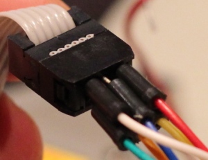
Yellow: MISO, Red: Vcc, Orange: SCK, Blue: MOSI, Green: Reset, White: GND
Below you can see how I connected all the pins from the programmer to the chip. This is the simple project from chapter 1 of the Evil Genius book. But the important thing here is how the cables are connected from the programmer to the ATtiny13 chip, because that is all you need. You do not need the LEDs, buttons, resitors and capacitor I put in.
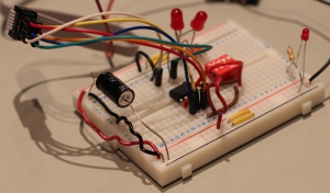
Simple setup from Evil Genius book. Allows us to turn on toggle to LEDs with push buttons.